
THE IMPEDANCE OF SPEAKERS
In this lesson we'll try to destroy the myth which the impedance of a speaker would correspond to as stated by the builder. In our opinion, to believe in rubbish as this is the same as believing that children are carried by the stork.
Actually the nominal impedance, that
specified on catalogs, has the only purpose to divide speakers in
families, depending on the type of use which they are intended for.
So we'll have 4Ω speakers for car-audio,
8Ω speakers for home
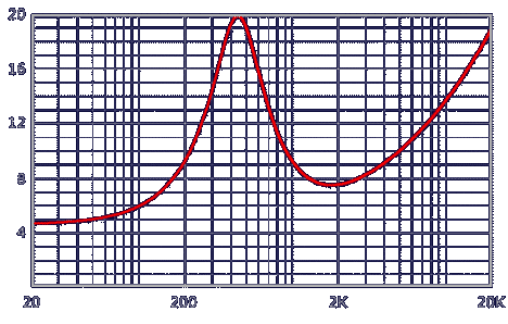
It is possible to describe the impedance assumed by the moving coil at different frequencies in graphical form on a cartesian plan, with the scale of frequencies in abscissa (Hz) and the impedance values in ordinate (Ω). The drawing that results is called an impedance curve and visually represents the modification of the ohmic value assumed by impedance at different frequencies. See for example that of a cone midrange rated for 6Ω nominal:

The first thing you notice is a peak of impedance with an ascending front and a descending front specular between them (well, this specularity is verifiable only if the frequency scale in abscissa is logarithmic). To it corresponds the resonance frequency of the component, recognizable exactly because at the resonance all transducers show a sudden increase of impedance. Moving toward the right, that's going up with the frequency, we meet a saddle where it should be possible to read a value near to that declared as nominal — see what has already been said about some builders — after which the effect of the moving coil inductance begins to make itself felt, in the form of a gradual increase of measurable impedance.
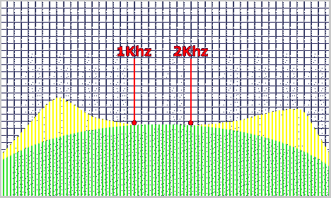
Through the graph below you can realize as a generic second-order bandpass calculated with the provided formulas produces definitely different responses if closed on a resistor (green) or on a real midrange (yellow):

Both to resonance of the midrange
and to the highest frequencies, the filter sees a greater load
impedance and filters less. Result: the curves are equal only in the
octave
To make the response of the set filter/speaker coincide to the model theorized by formulas it must modify the speaker in order to achieve in its terminals an impedance as much resistive as possible, that's constant with the frequency. Provide to this really them, the equalization networks
