
THE ATTENUATION CELLS
Among the characteristics of a speaker, is
its sensitivity to inform us about its attitude to play more or
less strong. In technical literature it is expressed by the symbol
dBspl (sound pressure level)
and measure — yeah, in decibels — the
level of sound pressure 1 meter away with an input of 2.83 volts.
Sensitivity is tied to other fundamental parameters such as the force
factor of the magnetic unit (Bl), the surface of diaphragm
(Sd), the direct current resistance
of the
dBspl = 88.49+20*log10(Bl*Sd/(Re*Mms))
which shows us, radiant surface being equal, that the sensitivity of a speaker can be increased by:
- strengthening its magnet,
- decreasing its moving mass,
- reducing its voice-coil electrical resistance.
This last method is definitely economical in implementation and although it dangerously forces the voice-coil toward its breaking point, some manufacturers make brazen recourse to it to sell for more what has cost less for them.
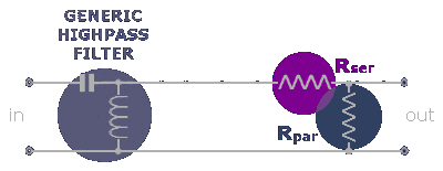
As it regards us, the true sense of the formula is that being the moving mass at denominator the more it decreases the stronger the speaker will play. The most evident result is that under the same conditions a small speaker will play stronger than a large speaker, that is speakers for the mid-highs and highs are generally the most sensitive. Don't be surprised therefore if this damn tweeter will play stronger than the woofer and don't lose hope, there's a way out. Well, there are actually two ways out. In the first case it's to interpose a resistor between filter and tweeter, in series with this one, according to the following scheme:

The wattage of the resistor will be proportional to the power it has to handle and its ohmic value is calculable with this formula:
Rser = Ztw*(10a/20-1) [Ω]
where a is the difference in sensitivity between the two speakers and Ztw the impedance of the speaker to attenuate. Notice we are supposing this is a tweeter just as an example — it could be any speaker. Notice carefully that in this way the filter will not be loaded only on the tweeter but on the combination of this one plus the resistor. Therefore you'll need to re-parameterize the filtration network considering the new impedance:
Ztot = Ztw+Rser [Ω]
A second method which has the undeniable advantage in bringing about no variations in the native filter network, is to put a second resistor next to the first one, in parallel with the speaker, according to the following scheme:

This second resistor will also be of appropriate power and its value is given by the relationship
Rpar = Ztw*(1+Ztw)/Rser [Ω]
As already said this solution allows us to keep the filter intact, as Rpar restores its original load. For this reason it is particularly advisable when you work afterwards on already made filters.
There is however a particular filter that all in one go operates both the cut and the attenuation, that's the RL filter
